


Description

Key Features
-
400V (IGBT) / 800V (SiC) Maximum DC bus voltage
-
30A Maximum AC current, 15kW power handling
-
50kHz (IGBT) / 200kHz (SiC) switching frequency
-
Hardware OVP, OCP, OTP, SCP protection with auto-recovery
-
4 Fiber optic PWM inputs + 1 fault output
-
Integrated DC voltage and AC current sampling
-
800ns hardware dead-time prevents shoot-through
-
CPLD-based logic for microsecond protection response
Product Details
Overview
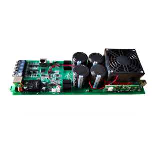
The JMFB01 is a high-performance, single-phase H-bridge power module engineered for demanding power electronics applications. It can be deployed independently or integrated into complex systems, offering both optical fiber and Ethernet data transmission methods for maximum architectural flexibility.
To ensure data transmission reliability, the module incorporates extensive isolation chips and advanced anti-interference processing. It features integrated gate drive circuits, PWM hardware dead-time logic, analog signal sampling, and robust hardware protection. This high level of integration makes the module ideal for constructing various converter architectures, including multilevel power topologies.
A dedicated CPLD chip logically processes all digital signals, ensuring the power module functions strictly within safe operating limits. The board is compatible with any external controller and seamlessly supports MATLAB/Simulink rapid control prototyping platforms for immediate algorithm validation.
Connections
Power Connections:
DC bus terminals (DC+ and DC-), Midpoint terminals (AC1 and AC2)
Signal Connections:
PWM signal input (Optical Fiber Receiver), Fault feedback signal (Optical Fiber Transmitter), DC voltage and AC current sampling (RJ45)
Auxiliary Connections:
NTC10K temperature sensor, integrated cooling fan with automatic temperature control
Typical Applications
- 2-level Inverter / Converter
- DC/DC Converter
- Modular Multilevel Converter (MMC)
- Cascaded H-bridge (CHB)
- Dual Active Bridge (DAB)
- Active Front End (AFE) Rectifier
- Battery Test Systems
- R&D / Rapid Prototyping
Dual Technology Options
Choose between proven IGBT technology (600V/50A, 50kHz) or cutting-edge SiC (1200V/50A, 200kHz). Both options feature identical interfaces for seamless technology upgrades without redesign.
Comprehensive Protection
CPLD-based hardware protection responds in microseconds. Includes desaturation detection, OVP, OCP, and OTP with soft shutdown and automatic 2-second fault recovery.
Fiber Optic Isolation
Full galvanic isolation between control and power circuits via a fiber optic PWM interface. Supports Ethernet daisy-chaining for easy multi-module system expansion.
Overview
The JMFB01 is a high-performance single-phase H-bridge power module designed for demanding power electronics applications. It can be used independently or integrated into complex systems, providing both optical fiber and Ethernet data transmission methods for maximum flexibility.
The module incorporates extensive isolation chips and anti-interference processing to enhance data transmission reliability. It integrates gate drive circuits, PWM hardware dead-time circuits, analog signal sampling, and hardware protection functions. This highly integrated hardware functionality makes the module ideal for building various converter architectures including multilevel power topologies.
A CPLD chip processes all digital signals logically to ensure the power module operates within safe operating ranges. The power board module can be driven by any external controller, and is fully compatible with MATLAB/Simulink rapid control prototyping platforms for immediate algorithm validation.
Connections
Power Connections: DC bus terminals (DC+ and DC-), Midpoint terminals (AC1 and AC2)
Signal Connections: PWM signal input (optical fiber receiver), Fault feedback signal (optical fiber transmitter), DC voltage and AC current sampling (RJ45)
Auxiliary Connections: NTC10K temperature sensor, Integrated cooling fan with automatic temperature control
Specifications
| Parameter | IGBT Version | SiC Version |
|---|---|---|
| Maximum DC Bus Voltage | 400V | 800V |
| Power Device Rating | 600V / 50A | 1200V / 50A |
| Maximum AC Current | 30A | 30A |
| Maximum Output Power | 15kW | 15kW |
| Maximum Switching Frequency | 50kHz | 200kHz |
| Hardware Dead-time | 800ns | 800ns |
| PWM Channel Selection | 2-channel / 4-channel (software configurable) | |
| Topology Support | Half-bridge / Full-bridge (software configurable) | |
| Event | Trigger Threshold | Recovery Threshold |
|---|---|---|
| Overvoltage (OVP) | VDC > 420V / 820V | VDC < 360V / 760V |
| Overcurrent (OCP) | |IAC| > 60A | |IAC| < 60A |
| Overtemperature (OTP) | TEMP > 75°C | TEMP < 65°C |
| Short Circuit (SCP) | Vdesat > 6.5V | — |
| Fan Control | TEMP > 55°C | TEMP < 45°C |
| Interface | Description |
|---|---|
| Optical Fiber Input | 4 channels (PWM1A, PWM1B, PWM2A, PWM2B) |
| Optical Fiber Output | 1 channel (Fault feedback – FO) |
| Ethernet Interface | 1 input + 1 output (RJ45 daisy-chain) |
| Analog Feedback | DC voltage + AC current sampling (RJ45) |
| Status Indicators | 4 LED (OVP, OCP, OTP, SCP) + Power + Operation |
Interface Definition
| Signal | Definition |
|---|---|
| PWM1A | Bridge arm A upper switch drive signal (2PWM: Bridge arm A input) |
| PWM1B | Bridge arm A lower switch drive signal |
| PWM2A | Bridge arm B upper switch drive signal (2PWM: Bridge arm B input) |
| PWM2B | Bridge arm B lower switch drive signal |
| FO | Fault feedback signal (active when any protection triggers) |
| Pin | Definition |
|---|---|
| 1 | Signal reference ground |
| 2 | Signal reference ground |
| 3 | Fault open-drain output E |
| 4 | Fault open-drain output C |
| 5 | Bridge arm A upper switch drive signal |
| 6 | Bridge arm A lower switch drive signal |
| 7 | Bridge arm B upper switch drive signal |
| 8 | Bridge arm B lower switch drive signal |
| Pin | Definition |
|---|---|
| 1 | DC bus voltage sampling value |
| 2 | Analog ground |
| 3 | AC current sampling value |
| 4 | Analog ground |
| 5 | 0V |
| 6 | 24V power supply |
| 7 | 0V |
| 8 | 24V power supply |
Support
Hardware Protection Functions
CPLD-based protection responds faster than software, keeping your power devices safe
DC bus voltage monitoring with automatic recovery when voltage drops below threshold
AC current monitoring with soft shutdown and 2-second auto-recovery
NTC10K sensor monitors heatsink temperature with 10°C hysteresis
Desaturation detection catches shoot-through in nanoseconds
Request a Quote
Interested in the JMFB01 power module for your application? Contact us for pricing, lead times, and technical support. Our engineering team is ready to help you integrate this module into your power conversion system.
Reviews
There are no reviews yet.